Dream DRM Receiver


Simulated Receiver Performance
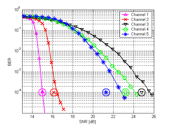
Bit-Error-Rate (BER) simulations on all DRM channels
All simulations are made in compliance with the DRM standard Annex A (Robustness
mode A for channels 1 and 2, mode B for channels 3-5. The code rate is R = 0.6, the
modulation is 64-QAM).

The curves represent the overall performance of the receiver. The encircled markers at a BER of 10-4 are the results given for ideal channel estimation.

Multilevel Decoder
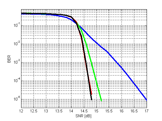
The multilevel decoder was tested in compliance with the parameters given in the
DRM-standard in Annex A. We simulated the channel 1 (AWGN) with robustness mode A,
a code rate of R=0.6, 64-QAM and 10kHz bandwidth. The equivalent bandwidth of the
noise is 10kHz.

Blue line: one iteration, green line: two iterations,
red line: three iterations, black line: four iterations.
As seen in the plot, a BER of 10-4 is achieved at an SNR of approximately 14.9dB which is the same value given in table A.1 in the DRM-standard (using two iterations).

Blue line: one iteration, green line: two iterations,
red line: three iterations, black line: four iterations.
Channel Estimation in Frequency Direction
The following parameters were used in this simulation:
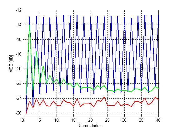
Robustness mode B, 10kHz bandwidth, 20dB SNR, channel No. 3 (US Consortium)
The mean squared error (MSE) between the estimated channel and an ideal channel estimation is plotted.

Robustness mode B, 10kHz bandwidth, 20dB SNR, channel No. 3 (US Consortium)
The mean squared error (MSE) between the estimated channel and an ideal channel estimation is plotted.
- Blue line: Linear interpolation: We lose approx. 7dB on the carriers without pilots.
- Green line: Windowed DFT algorithm: Almost the same performance on carriers with and without pilots but problems at the edge of the spectrum.
- Red line: Wiener interpolation (using all pilot carriers for each interpolated cell): Nearly equal performance on all carriers, approx. 1dB better than DFT and linear interpolation.

Last modified: 2005-06-30

